In the high-stakes environment of electrical engineering, the longevity and operational reliability of switching devices—ranging from miniature signal relays to heavy-duty industrial contactors and circuit breakers—rest heavily upon the performance of their electrical contacts. While the metallurgical composition of these contacts, such as Silver Tin Oxide (AgSnO2), Silver Nickel (AgNi), or Silver Tungsten (AgW), is frequently the focus of technical discussion, the physical geometry of the contact rivet head is a factor of equal, if not superior, importance. The geometric profile of a contact determines how an electrical arc is initiated, how thermal energy is dissipated throughout the rivet body, and how material migration occurs over millions of switching cycles. This technical analysis explores the complex relationship between contact geometry, arc erosion dynamics, and the strategic optimization of electrical life.
The Fundamentals of Contact Geometry Profiles
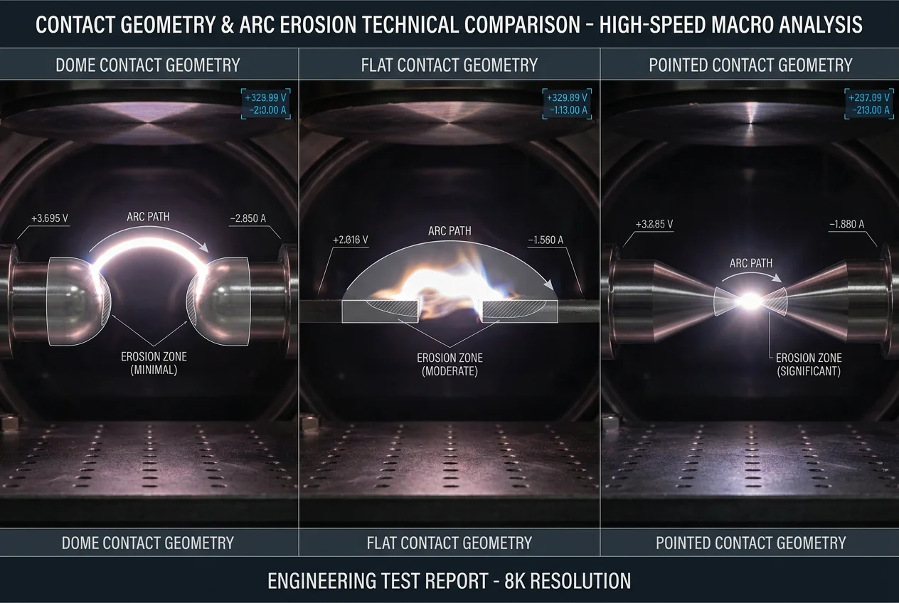
Electrical contact rivets are generally engineered into three foundational head geometries: flat, dome (spherical), and pointed (conical). Each profile is designed to address specific mechanical and electrical challenges inherent in switching loads. Understanding the nuances of these shapes is the first step in maximizing component performance.
Flat Contacts: The Pursuit of Surface Area
Flat-headed rivets are designed with the intention of providing the maximum possible nominal contact area. In a theoretical vacuum, a flat-to-flat contact interface should yield the lowest possible constriction resistance (Rc). However, the physical reality of mechanical manufacturing means that achieving absolute parallelism between two opposing flat surfaces is nearly impossible. Even a microscopic misalignment of 0.1 degrees results in the contact interface being reduced to a single “edge” or “corner” contact. This leads to a massive concentration of current at a single point, causing extreme localized heating and premature arc erosion. Flat contacts are therefore best suited for high-current applications where the mechanical assembly is exceptionally rigid and precisely aligned, allowing for superior heat sinking once the contacts are fully seated.
Dome (Spherical) Contacts: The Industry Standard for Versatility
The dome-shaped contact rivet is the most widely utilized geometry in the electrical industry. By incorporating a specific spherical radius—typically ranging from R2.0 to R10.0 depending on the application—the dome ensures a consistent contact point regardless of minor mechanical misalignments. When two dome contacts (or a dome and a flat contact) meet, they create a well-defined contact patch that expands slightly under mechanical load. This “self-centering” characteristic is vital for maintaining stable contact resistance over the life of the device. Furthermore, the curved surface of the dome allows for more efficient “venting” of the ionized gases produced during arcing, preventing the arc from becoming trapped and causing excessive localized pitting.
Pointed (Conical) Contacts: Precision in Contaminated Environments
Pointed or conical contacts are specialized tools for low-force applications. Their sharp geometry is designed to generate high contact pressure at the very tip, which is effective at “piercing” through surface oxides, dust, or silicone contamination layers that might otherwise cause a failure to conduct. While excellent for signal integrity, pointed contacts have a very low thermal mass at the interface. This makes them highly susceptible to melting and vaporization if subjected to even moderate arcing, limiting their use to low-power signal switching or specialized auxiliary circuits.
The Physics of Contact Area vs. Arc Density
The core challenge in extending electrical life is the management of the electrical arc’s energy density. When a pair of contacts begins to separate, the current flow is constricted into a decreasing number of microscopic “a-spots” (asperities). This constriction causes a rapid rise in temperature, eventually melting a small bridge of metal. As this bridge breaks, an arc is ignited. The “effective contact area” is not the entire head of the rivet, but rather the sum of these microscopic conducting spots.
Arc density, defined as the current magnitude per unit of the conducting area, is the primary driver of material loss. High arc density results in temperatures that far exceed the boiling point of silver alloys (approx. 2162°C). This causes the material to vaporize and be lost to the surroundings. A dome geometry helps mitigate this by ensuring that the arc is initiated in a predictable central zone. By optimizing the dome radius, engineers can effectively “spread” the arc’s heat over a larger volume of the rivet head, utilizing the bulk material as a heat sink and reducing the peak temperature at the surface.
Erosion Mechanisms and the Influence of Shape
Contact erosion is a multi-stage process involving vaporization, melting/splashing, and material transfer. Geometry plays a distinct role in each:
1. **Thermal Sinking and Vaporization**: The volume of the rivet head directly beneath the contact point acts as a thermal reservoir. A larger, thicker head geometry (common in flat rivets) can absorb more energy before reaching the vaporization threshold. However, if the heat cannot be moved away from the interface quickly enough, vaporization will occur regardless of volume. This is why bimetal rivets (silver layer on a copper shank) are so popular; the copper shank provides a high-thermal-conductivity path to the contact carrier.
2. **Molten Pool Retention**: Under heavy arcing, the contact surface becomes a pool of liquid metal. In flat contacts, especially those with edge contact, this liquid metal can easily “run off” the side of the rivet, resulting in permanent material loss. Dome geometries tend to keep the molten pool centered within the “bowl” of the contact area, increasing the likelihood that the metal will resolidify in place rather than being lost.
3. **Managing Material Transfer (Fine Migration)**: In DC circuits, current flows in one direction, causing material to systematically move from the anode to the cathode (or vice versa). This results in the formation of “pips” (deposits) and “craters” (holes). A common engineering strategy is to use a dome contact as the anode and a flat contact as the cathode. The flat surface can accommodate a significant “pip” from the dome without drastically changing the contact resistance, whereas two domes would quickly become unstable as a pip grows on one side.
Engineering Optimization for Maximum Electrical Life
To achieve the 30-post plan’s goal of technical excellence, we must consider several optimization strategies for contact geometry:
– **The Radius-to-Diameter Ratio**: For most power relays, a dome radius that is 3 to 5 times the head diameter is ideal. This provides enough curvature to be tolerant of misalignment while remaining “flat” enough to provide a substantial contact patch under pressure.
– **Surface Micro-Geometry**: While the macro-shape (dome/flat) is important, the surface finish also matters. A polished surface reduces the number of initial arc triggers, but a controlled “matte” finish can actually help stabilize the arc’s root point, preventing it from wandering and causing erratic erosion patterns.
– **Alignment and Overtravel**: Geometry cannot solve a mechanical failure. Engineers must ensure that the “overtravel” (the distance the actuator moves after the contacts first touch) is sufficient to create the required mechanical pressure to flatten the a-spots and establish a stable Rc. A dome contact requires slightly more overtravel than a flat contact to achieve the same effective area.
Conclusion: Shaping the Future of Reliability
In conclusion, the geometry of an electrical contact is a fundamental pillar of its performance, as critical as the material it is made from. By selecting the appropriate profile—whether it be the precision of a dome, the area of a flat, or the penetration of a point—and balancing arc density against thermal management, engineers can significantly extend the electrical life of their components. As switching devices continue to shrink in size while handling higher power densities, the science of contact geometry will remain at the forefront of electrical manufacturing excellence.