Contact Welding in Relays: Causes, Prevention & Material Selection (2026)
Contact welding—also called contact fusion or contact sticking—is one of the most common failure modes in electromechanical relays and switches. It occurs when the contact surfaces fuse together under the heat and pressure of switching, rendering the device permanently closed even when the coil is de-energized.
For manufacturers of relays, contactors, and switches, understanding the root causes of contact welding and selecting contact materials that resist fusion is critical to product reliability and safety.
In this guide, we explain why contacts weld, the factors that increase welding risk, and how material selection can prevent this costly failure mode.
—
What Is Contact Welding?
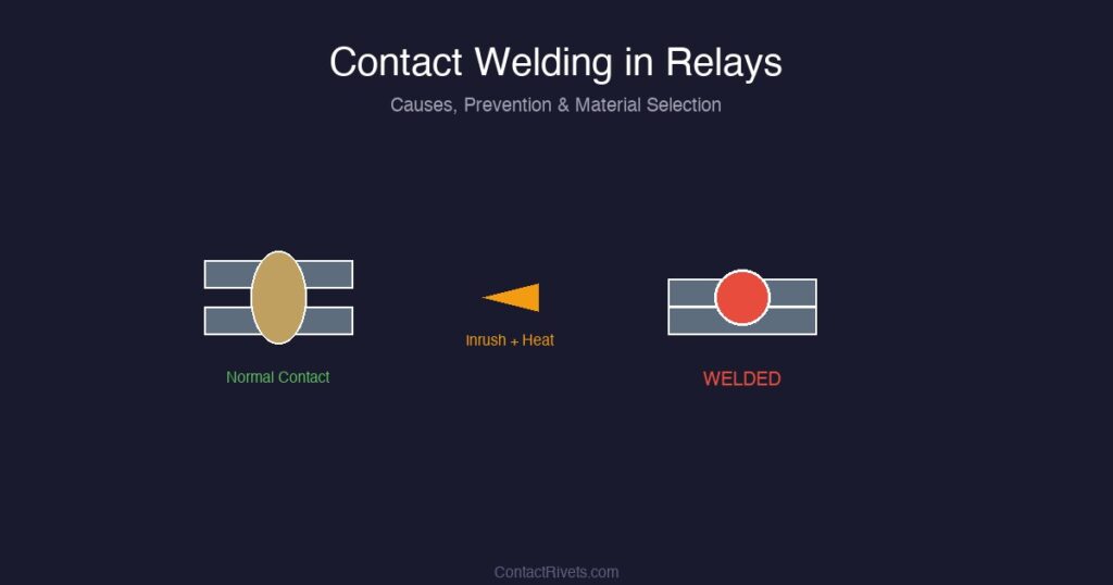
Contact welding is the fusion of two mating contact surfaces into a single metallic bond. It occurs when:
- Joule heating at the contact interface raises the local temperature above the melting point of the contact material.
- Mechanical pressure from the contact spring or magnetic force holds the molten surfaces together.
- Solidification occurs before the contacts separate, creating a permanent bond.
Once welded, the contacts cannot open under normal spring force. The relay or switch fails “closed”—a dangerous condition that can cause equipment damage, fire, or safety hazards.
Types of Contact Welding
| Type | Cause | Typical Scenario |
|---|---|---|
| Static welding | Excessive current through closed contacts | Short circuit downstream of relay |
| Dynamic welding | Arc energy during closure under load | Motor starting, capacitor charging |
| Bounce welding | Repeated micro-arcs during contact bounce | High-inrush loads, loose contacts |
—
What Causes Contact Welding?
1. High Inrush Current
The most common cause of dynamic welding is switching loads with high inrush currents. When a relay closes into an inductive or capacitive load, the initial current surge can be 5–15× the steady-state value.
Typical inrush currents:
- Incandescent lamps: 10–15× steady-state current (cold filament resistance is very low)
- Motors: 6–10× full-load current during startup
- Transformers: 20–40× rated current for the first half-cycle (magnetizing inrush)
- Capacitors: Limited only by circuit resistance; can be extremely high
The high current density at the initial contact point creates localized melting and fusion.
2. Insufficient Contact Force
Low contact force reduces the real contact area (the microscopic spots where current actually flows), increasing current density and Joule heating. It also reduces the mechanical energy available to break a forming weld.
3. Contact Material Properties
Soft, pure materials like fine silver weld more readily than hard, oxide-dispersed materials. The presence of refractory oxide particles (SnO₂, CdO, Ni) in the contact matrix interrupts fusion by creating physical barriers between mating metal surfaces.
4. Contact Bounce
When contacts close, mechanical bounce can cause repeated make-break cycles within milliseconds. Each bounce generates a micro-arc that erodes material and can initiate fusion if the arc energy is sufficient.
5. Contamination
Oxide films, sulfide layers, or organic contaminants on contact surfaces increase contact resistance and localized heating. In severe cases, contaminants can carbonize and create conductive bridges that promote welding.
—
Anti-Welding Contact Materials
Material selection is the most effective strategy for preventing contact welding.
AgSnO₂ (Silver-Tin Oxide)
AgSnO₂ contacts offer the best anti-welding performance among RoHS-compliant materials. The hard SnO₂ particles dispersed in the silver matrix create a microscopically rough surface that prevents large-area metal-to-metal fusion.
Anti-welding rating: Excellent (5/5)
Best for: Motor controls, lamp switching, inductive loads, high-inrush applications.
AgNi (Silver-Nickel)
AgNi provides moderate anti-welding performance. The nickel phase increases hardness compared to pure silver but is less effective than tin oxide at interrupting fusion under severe inrush.
Anti-welding rating: Moderate (2–3/5)
Best for: Resistive loads, light-duty relays, applications with minimal inrush.
AgCdO (Legacy)
Historically, AgCdO was the gold standard for anti-welding. The CdO phase provides exceptional resistance to fusion under peak inrush currents. However, cadmium is now restricted under RoHS.
Anti-welding rating: Excellent (5/5)
Status: Being phased out; replaced by AgSnO₂.
AgC (Silver-Graphite)
The graphite phase in AgC acts as a solid lubricant during arcing, preventing material transfer and welding. This makes AgC particularly effective for DC switching where material transfer is unidirectional.
Anti-welding rating: Excellent (5/5) for DC
Best for: DC pre-charge relays, battery disconnect switches, DC circuit breakers.
—
Design Strategies to Prevent Welding
Beyond material selection, several design strategies reduce welding risk:
- Increase contact force: Higher force increases real contact area, reducing current density and heating. Typical relay contact forces range from 0.5 N (signal relays) to 50+ N (power contactors).
- Use multi-contact arrays: Distributing current across multiple parallel contact pairs reduces current per contact and provides redundancy.
- Add current limiting: Series resistors, NTC thermistors, or soft-start circuits reduce inrush current during closure.
- Optimize contact geometry: Radius (domed) contacts create point contact with high local pressure that breaks oxide films without large fusion area.
- Control contact bounce: Damping mechanisms, magnetic blowout, or optimized spring rates minimize bounce duration and arc energy.
- Specify adequate contact gap: Larger gaps increase arc voltage and reduce reignition probability after initial extinction.
—
Testing for Welding Resistance
IEC 60947 and UL 508 specify welding resistance tests where relays are subjected to:
- Make-only tests: Contacts close into a short-circuit or high-inrush load; must open when coil de-energized.
- Endurance tests: 10,000–1,000,000 operations at rated load; no welding allowed.
- Overload tests: 6–10× rated current for specified cycles; contacts must remain functional.
—
Conclusion
Contact welding is a preventable failure mode. By understanding the root causes—high inrush current, insufficient contact force, and material properties—engineers can select the right contact materials and design parameters to ensure reliable switching.
For applications with significant inrush or inductive loads, AgSnO₂ is the material of choice, offering anti-welding performance that matches or exceeds legacy AgCdO while maintaining RoHS compliance.
—