Electrical Contact Resistance: What Affects It & How to Minimize It (2026)
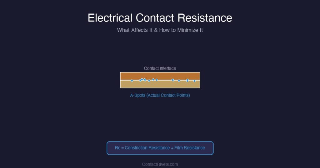
Electrical contact resistance is the resistance encountered by current as it passes through the interface between two mating contacts. Even when contacts appear to be in firm mechanical contact, current flows only through a small number of microscopic “a-spots” (asperity spots), creating a localized resistance that generates heat and voltage drop.
For relay and switch designers, managing contact resistance is essential. Excessive resistance causes overheating, energy loss, and premature contact failure. Understanding what affects contact resistance—and how to minimize it—enables better material selection and mechanical design.
—
What Is Contact Resistance?
Contact resistance (R_c) is the sum of two components:
- Constriction resistance: Current must constrict from the bulk conductor into the microscopic a-spots where actual metal-to-metal contact occurs. This constriction creates a resistance proportional to the resistivity of the contact material and inversely proportional to the radius of the a-spots.
- Film resistance: Oxide layers, sulfide films, or organic contaminants on contact surfaces add a resistive barrier. Even nanometer-thick oxide films can significantly increase resistance for low-force contacts.
The total contact resistance is measured in milliohms (mΩ) and depends on contact material, surface condition, contact force, and temperature.
—
Factors That Affect Contact Resistance
1. Contact Material
Different contact materials exhibit different inherent resistivity and film-forming tendencies:
| Material | Bulk Resistivity | Typical Contact Resistance | Film-Forming Tendency |
|---|---|---|---|
| Pure Silver | 1.6 μΩ·cm | <1 mΩ | Moderate (sulfide in H₂S) |
| AgNi | 2.0–2.5 μΩ·cm | 1–2 mΩ | Low |
| AgSnO₂ | 2.5–4.0 μΩ·cm | 2–5 mΩ | Very low |
| AgW | 5–8 μΩ·cm | 5–20 mΩ | Very low |
| AgC | 3–5 μΩ·cm | 3–10 mΩ | Very low (graphite barrier) |
2. Contact Force
Higher contact force increases the real contact area by deforming surface asperities and breaking through oxide films. Contact resistance typically follows an inverse relationship with force:
R_c ∝ F^(-n) where n ≈ 0.5–1.0 depending on material hardness.
Typical contact forces:
- Signal relays: 0.1–0.5 N
- Power relays: 1–10 N
- Contactors: 10–100 N
3. Surface Condition
Clean, polished contact surfaces exhibit lower resistance than oxidized or contaminated surfaces. Even brief exposure to air can form oxide films on copper and silver contacts.
Mitigation strategies:
- Gold plating for low-current signal contacts
- Hermetic sealing for critical aerospace relays
- Contact wipe (sliding motion during closure) to break oxide films
4. Temperature
As contact temperature rises, material resistivity increases and contact force may decrease due to thermal expansion of the spring or housing. This creates a positive feedback loop where higher resistance causes more heating, which further increases resistance.
The maximum allowable temperature rise is typically limited to 40–60 K above ambient for standard relays and 80–100 K for heavy-duty contactors.
5. Contact Geometry
- Flat contacts: Large area but sensitive to contamination; best for high-force applications.
- Radius (domed) contacts: Point contact with high local pressure; breaks oxide films effectively.
- Crossed rods: Line contact; good for test fixtures but rarely used in production devices.
—
How to Minimize Contact Resistance
- Select low-resistivity materials: For signal and low-current applications, pure silver or AgNi offers the lowest contact resistance.
- Optimize contact force: Ensure sufficient force to create adequate a-spot area without excessive spring loading that reduces mechanical life.
- Use contact wipe: Design contacts with 0.5–2.0 mm of sliding motion during closure to break oxide films and clean the interface.
- Protect against contamination: Enclose contacts in sealed housings for harsh environments; use dust covers for industrial applications.
- Match materials: Avoid pairing dissimilar metals with large galvanic potential differences; use compatible contact pairs (Ag-Ag, AgNi-AgNi).
- Verify with measurement: Use four-wire (Kelvin) measurement techniques to accurately measure contact resistance during prototype testing.
—
Measuring Contact Resistance
The standard method for measuring contact resistance is the four-wire (Kelvin) technique:
- Force a known DC current (typically 1–10 A) through the closed contact.
- Measure the voltage drop across the contact interface using separate sense leads.
- Calculate resistance: R = V / I.
This method eliminates lead resistance and provides accurate measurement of the contact interface resistance alone.
—
Conclusion
Electrical contact resistance is determined by a complex interaction of material properties, mechanical force, surface condition, and temperature. By selecting appropriate contact materials, optimizing contact force, and controlling surface condition, designers can achieve reliable, low-resistance switching that meets thermal and efficiency requirements.
For applications where minimal contact resistance is critical—such as signal relays, measurement circuits, and high-efficiency power switching—pure silver and AgNi contacts offer the best performance. For high-current or harsh-environment applications, the slightly higher resistance of AgSnO₂ or AgW is a worthwhile trade-off for superior arc resistance and durability.
—