Electrical contacts are the critical interface in any switching device, from miniature relays to massive industrial contactors. When these interfaces fail, the consequences can range from minor system glitches to catastrophic electrical fires. Failure analysis is not just about identifying what went wrong; it is about understanding the metallurgical and electrical physics to prevent future occurrences. This technical breakdown examines the most common failure modes—welding and material transfer—and provides engineering solutions for silver-based contacts.
Failure Mode 1: Dynamic Welding (The “Make” Failure)
Dynamic welding occurs when the contacts close. As the surfaces approach, the electric field becomes intense enough to initiate an arc before physical contact is made. This “pre-strike” arc melts a small volume of the silver alloy. If the contacts then bounce, as they often do due to mechanical inertia, the molten silver can bridge the gap and fuse upon solidifying.
To prevent premature welding, engineers must focus on both mechanical design and material selection. Increasing the contact force can help break small micro-welds, but the ultimate solution lies in the alloy. Silver Tin Oxide (AgSnO2) is significantly more resistant to dynamic welding than pure silver or AgCdO because the tin oxide particles remain solid at the temperatures that melt silver, creating a mechanical barrier that prevents fusion.
Failure Mode 2: Arc Erosion and Pitting (The “Break” Failure)
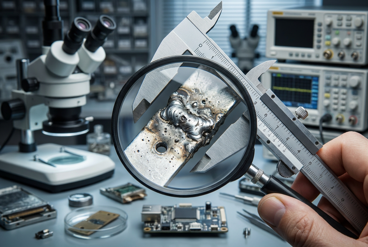
Every time a circuit is broken, an arc is formed. This arc vaporizes the contact material, leading to a gradual loss of substance—a process known as arc erosion. Over time, this erosion creates deep pits and craters, which increase the contact resistance and eventually lead to mechanical sticking or dielectric failure.
Metallurgical solutions for arc erosion involve the use of advanced dopants like Indium Oxide (In2O3) or Tungsten (W). These additives refine the grain structure and increase the thermal stability of the silver matrix. By ensuring that the arc moves rapidly across the surface (improving arc mobility), the thermal load is distributed, and the rate of material loss is significantly reduced.
Failure Mode 3: Material Transfer in DC vs. AC Circuits
Material transfer, or the “pip and crater” effect, is a common failure mode in DC circuits. Because the current flows in only one direction, ions are consistently transported from one electrode (the anode) to the other (the cathode). In AC circuits, the reversing polarity tends to keep the material transfer balanced, but in DC, it can quickly lead to a bridge that prevents the contacts from opening.
Preventing material transfer in high-voltage DC applications, such as EV battery systems, requires specialized alloys that maintain a uniform surface topology. AgSnO2 with a high oxide content (12-14%) is particularly effective here, as the stable oxide particles inhibit the flow of the silver ions across the gap.
Inspection Protocols and Proactive Maintenance
Effective failure analysis relies on rigorous inspection protocols. Scanning Electron Microscopy (SEM) and Energy Dispersive X-ray Spectroscopy (EDS) are essential tools for identifying the distribution of oxides and the presence of contaminants on the contact surface. By monitoring the contact resistance and performing periodic visual inspections for signs of excessive pitting or discoloration, maintenance teams can replace components before they reach a critical state of failure.
Conclusion: Engineering for Reliability
The reliability of silver-based contacts is a function of metallurgical science, mechanical precision, and proactive maintenance. By understanding the physics behind dynamic welding, arc erosion, and material transfer, engineers can select the right materials and design parameters to ensure long-term, fail-safe operation. As electrical systems become more complex and power densities increase, the importance of robust failure analysis and metallurgical innovation will only continue to grow.